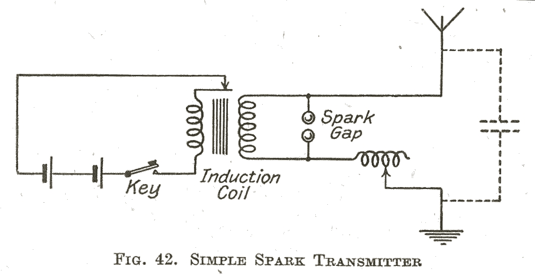
In essence, a radio transmitter is an antenna coupled to a tuned circuit that is maintained in a state of oscillation. Today we maintain this state using a transistor (or vacuum tube) circuit. A spark transmitter uses a spark gap to intermittently generate oscillations. When the capacitor in the tuned circuit is charged to a sufficiently high voltage, a spark is generated across the spark gap. This temporarily ionises the air in the path of the gap, making it conductive. Energy is exchanged between the inductive and capacitative elements until the spark can no longer be sustained. This usually amounts to only a few oscillations. A few moments later, the capacitor is recharged, and the process repeats. A simple analogy from acoustics would be a bell (tuned circuit) being regularly struck by its clapper (the spark).

In the simplest transmitters, the inductor may be a coil wound on an open frame, and the capacitor may be the natural capacitance between the antenna and ground. I measured it here, and it amounted to 750pF on my long wire antenna.
The high voltage (10 000 volts or more ) needed to charge the capacitor and generate a spark was produced by an induction coil, or from an alternator and step-up transformer.

The selectivity of the simple circuit just described left a great deal to be desired and it was not particularly efficient at coupling the generated power to the antenna. It tended to transmit on all frequencies at once.
Coupled Circuits
More complicated circuits used an antenna coupling transformer and a fixed capacitor to tune the transmitter to a given frequency. The antenna was coupled to the the secondary of the transformer and there was a further antenna tuning coil. Coupling the circuits correctly was essential, since under conditions of correct coupling, the secondary in the antenna circuit would resonate for a long period at the transmitted frequency. In a coupled circuit, close coupling produces a double peak in the tuning selectivity curve. Loose coupling produces a single peak and does not overload the primary circuit. The result of loose coupling is a cleaner transmission. This improvement, in turn, brought its own problems, since the air in the spark gap would not de-ionize quickly enough. The spark would last too long because of the reduced damping, resulting in poor transmitter efficiency.

Even though this arrangement reduced the bandwidth of the transmission considerably, it would not be acceptable today.
Spark gap Technology
For best results (maximum efficiency) the spark needs to be rapidly quenched. If this were not the case, in the case of the loosely coupled circuit, the spark would still be present when the next capacitor charge cycle occurred. There would also be problems with erosion of the spark gap. The transmitter output power increases with the rapidity with which the spark can be discharged.

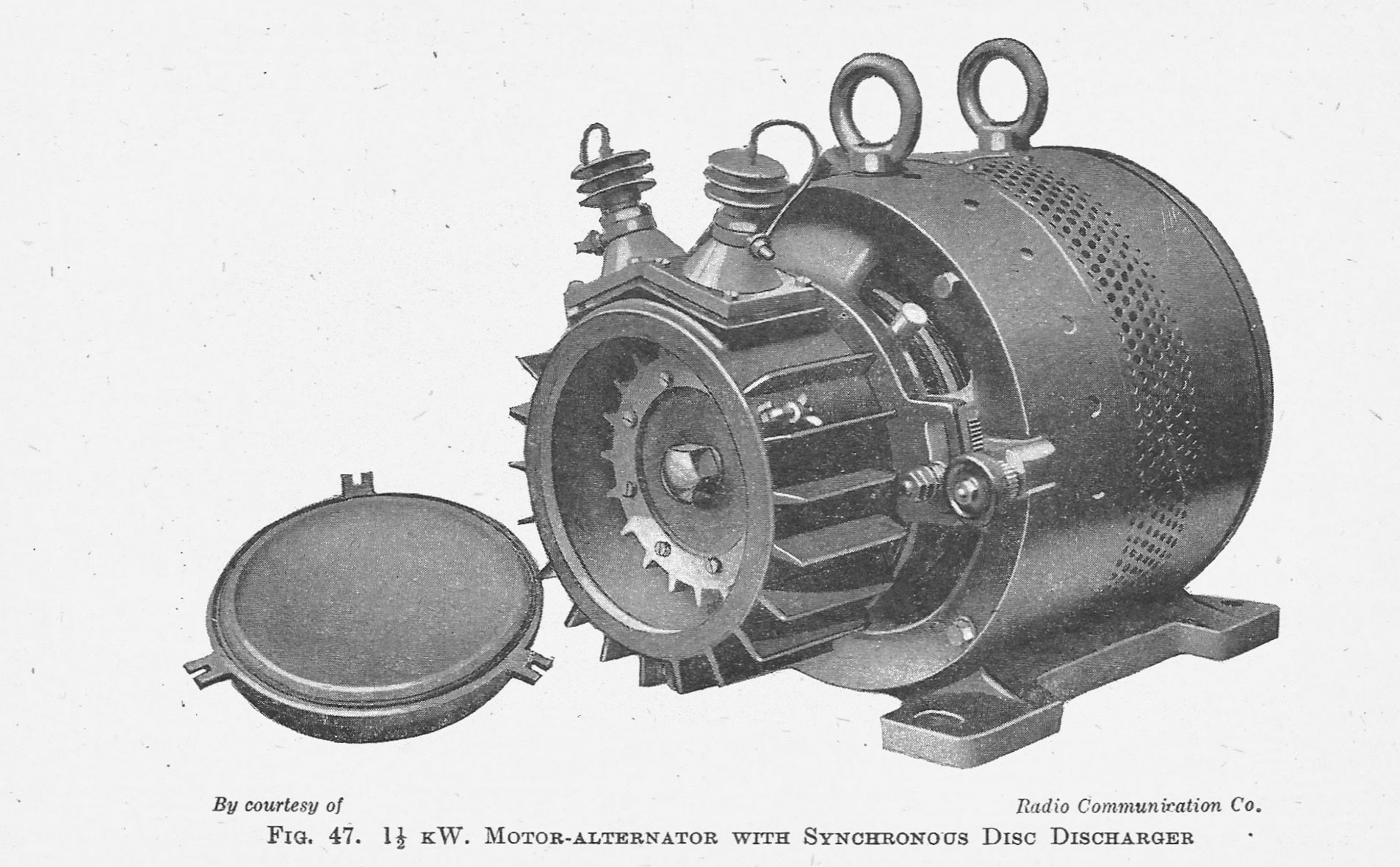
One way of achieving this was to use a rotary discharger. In effect, this is a rotating spark gap with electrodes attached to the rotor of the alternator. In the photograph, you will see it looks like a series of spikes that line up to the high voltage secondary connections. In a synchronous discharger, the number of spikes were arranged in such a way that at the correct rotational speed, each spike received a turn at discharging the spark in a round robin arrangement. The high rotational speed had the additional advantage of preventing ionisation by moving the air rapidly, which would otherwise prolong the spark.

Another scheme was the introduction of a self-quenching spark gap. This was a series of plates separated by mica insulators. The sparks would occur at random across the plates preventing ionisation. It was possible to operate the quenched spark transmitter at a very much higher spark frequency (1500Hz). The result sounds quite similar to a "modulated carrier wave" (MCW) transmission.
The photo below shows a quenched spark set.

This ships set used the rotary discharger - you can see it in the tray below.

Modulation and Keying
Whilst decent amplitude modulation of a spark transmitter was almost impossible, sending by means of Morse code was not difficult. For Morse sending, all that was required was to place the key in the primary of the transformer or induction coil circuit, as shown in the circuit diagrams. Although this was done, it wasn't particularly safe for the operator, particularly in the case of the alternator circuit.
The first AM broadcast was made by Reginald Fessenden in 1900 using a spark transmitter operating at 10 000 sparks/sec. The AM experimenters would often place a carbon microphone in series with the antenna. They were fearless indeed, for some of these microphones had to be water cooled. Fessenden's microphone was covered with asbestos.
From spark to modern times
The limitations of spark transmitters for telephony spurred on the development of HF alternators by Fessenden and Alexanderson. These were capable of generating a pure CW transmissions. There were also some experiments carried out with continuous arc transmitters. The triode valve was developed in 1907 by Lee de Forest. This made possible the continuous excitation of the transmitter tuned circuit and also made the amplification of speech possible. By the end of the 1920s, the spark transmitter had had its day and was only used for shipboard emergency transmissions.
References:
Reyner, "Radio Communication" 1945 edition, Pitman
Hammond Museum of Radio History (Online) hammondmuseumofradio.org - Here you can listen to the sounds of a reproduction spark transmitter
